Page 1 of 1
Programming Attiny 2313V
Posted: Wed Apr 08, 2015 1:38 pm
by idu14
I must start saying this is such a great kit! It is awesome, thank you for it! Building it, I figured out that it would be helpful if you would add extra info on how to enter into the Attiny 2313 microcontroller and program it.

I found some instructions on how to install drivers, and that was helpfull too, but not actually the steps on how to insert the code into the AVR. Searching on the internet, I found out that I need to use a software like Atmel Studio and a suitable hardware programmer. So I installed Atmel Studio, I can view the code (yeeey), and I also bought a programmer from ebay.

Mine is ATMEL AVR ATMega ATTiny 51 Development Board. I`ll attach a picture with it, I saw it is compatible and can program this type of AVR. The thing is this is the first time I am doing it, programming a microcontroller, I need to make some changes for my school project and I am not really sure on how to do it, the pinout, and how to make it come alive and I was hoping you could help me through or give me some ideas or info about. Thank you again for your time and such a great device!

Re: Programming Attiny 2313V
Posted: Wed Apr 08, 2015 1:57 pm
by mightyohm
Looks like you are off to a great start - let me know if you have any specific questions and I'll try to help!
Re: Programming Attiny 2313V
Posted: Wed Apr 08, 2015 2:34 pm
by idu14
Waw! Fast reply. Thank you for your help! I am not sure on how to make the connections to the ICSP connector. I found on the internet this 2 pinout schematics and I don`t know how to connect the programmer to the microcontroller and actually inject the code.

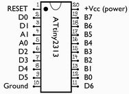

My programmer is the 10 PIN ISP version.
Re: Programming Attiny 2313V
Posted: Sun May 03, 2015 9:07 am
by mightyohm
J5 on the geiger counter has a pinout that matches the 6 pin connector that you showed. You just need to connect wires from the 10 pin connector on your programmer to the 6 pin connector on the geiger counter. Match the signals. Example: MISO is pin 1 on the 10 pin connector, and pin 1 on the 6 pin connector, so you would connect pin 1 to pin 1. SCK is pin 7 on the 10 pin connector, but pin 3 on the 6 pin connector, so you would connect a wire from pin 7 to pin 3.
One thing that can be tricky is that Atmel Studio only supports certain programmers, so you might need to use a 3rd party tool like avrdude to program a .hex file onto the ATTtiny2313.