SMD/ESP version
Posted: Mon Nov 05, 2018 9:11 pm
Hi All,
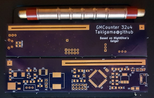
Recently got dumped a few GM tubes (im told they're a SBM-20) and i've always wanted to be able to see what I can do with one... There's a reasonable amount of info available, but alot is also quite hard to follow. Ultimately, i thought this one would be a good circuit to start with cause its probably the most compact/simple (not to mention one of the best schematics).
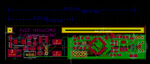
Having said that, im planning on making a USB and SMD version connected to either a atmega32u4 or an ESP8266 (or maybe an STM32), so i'll have 5v available and maybe 3.3v. I did find one post where someone had tried to do it (as well as a link to yet someone else's attempt) but with no resultant schematics or the like viewtopic.php?t=501 other than a suggestion that the STL128DN would be an smd capable component. Thats kinda where im stuck (one post i found was using a much lower spec'd transistor on the output for the job and claimed that it worked ok despite not being rated for the voltage).
Anyway, couple of questions I had, why does the output transistor need to be particularly quick at switching? I would have assumed you would need a pretty large number of pulses before that would matter much? I assume also that VR1 is really the thing that controls the voltage ultimately going to the tube? or should i be changing the input voltage to effect the output (or something else entirely)? What im really aiming for is something that can be adjusted for the various GM tubes that fall into that 400v above bracket that seem to be readily available. Lastly, everything i do is OSH so for better or worse, it'll end up on github.
Recently got dumped a few GM tubes (im told they're a SBM-20) and i've always wanted to be able to see what I can do with one... There's a reasonable amount of info available, but alot is also quite hard to follow. Ultimately, i thought this one would be a good circuit to start with cause its probably the most compact/simple (not to mention one of the best schematics).
Having said that, im planning on making a USB and SMD version connected to either a atmega32u4 or an ESP8266 (or maybe an STM32), so i'll have 5v available and maybe 3.3v. I did find one post where someone had tried to do it (as well as a link to yet someone else's attempt) but with no resultant schematics or the like viewtopic.php?t=501 other than a suggestion that the STL128DN would be an smd capable component. Thats kinda where im stuck (one post i found was using a much lower spec'd transistor on the output for the job and claimed that it worked ok despite not being rated for the voltage).
Anyway, couple of questions I had, why does the output transistor need to be particularly quick at switching? I would have assumed you would need a pretty large number of pulses before that would matter much? I assume also that VR1 is really the thing that controls the voltage ultimately going to the tube? or should i be changing the input voltage to effect the output (or something else entirely)? What im really aiming for is something that can be adjusted for the various GM tubes that fall into that 400v above bracket that seem to be readily available. Lastly, everything i do is OSH so for better or worse, it'll end up on github.